|
Serial Port Temperature Sensors - Serial Hardware Interface
This page describes the electronic circuitry required to interface
to the temperature sensors via a PC's serial port.
Both circuits shown below are implementations of Maxim/Dallas' reference
DS9097U 1-wire serial port interface.
If you don't have any serial ports on the PC you want to connect temperatures sensors to,
you can use a USB-serial adapter.
Schematic - Parasitic Mode Circuit
The serial port interface circuit was taken from page 21 of (an older revision of) the
Maxim Application Note 74: Reading and Writing iButtons via Serial Interfaces,
and redrawn by Martin using
Circad'98 for Windows.
This circuit is a generic circuit for communicating to any 1-wire device (in parasitic mode) via
a serial port, and works reliably with the DS18S20 temperature sensors.
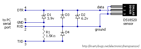
1-wire serial port interface circuit for parasitic mode operation
The circuit consists of four connections to the PC's serial port, two connections to the
temperature sensor, two zener diodes, two Schottky diodes and a resistor.
Due to the small number of components, it is possible to build a circuit that is small
enough to fit inside a plastic DB9 serial port shell.
Note that commercial versions of this circuit are readily available -
Maxim and
other vendors sell serial port and USB versions.
Component List - Parasitic Mode Circuit
The following components are required for the parasitic mode serial port interface circuit:
- DS18S20 1-wire temperature sensor
- D1 3.9v zener diode (1N5228 / 1N4730)
- D2 6.2v zener diode (1N5234 / 1N4735)
- D3,D4 Schottky diode (1N5818 / 1N5819)
- R1 1.5kohm resistor
- female DB9 serial cable
Note that D1 can be substituted with a 3.6v zener diode if necessary.
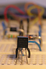
DS18S20 Sensor Pinout
For the DS18S20 sensor in a TO-92 package, the pins are, from left to right:
- GND - ground
- DQ - data in/out
- VDD - power supply voltage
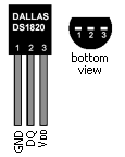
temperature sensor pinout
When operating in parasitic mode, the VDD terminal is not used, and needs to be grounded,
as the sensor sources required power from the data line.
Parasitic Mode Limitations
Apparently the wiring between the circuitry and the temperature sensor(s) can be extended up to
100 metres in parasitic mode.
For distances greater than this, you cannot use the sensor in parasitic mode, but you will
need to provide power to the VDD pin of the temperature sensor.
Running the sensor in parasitic mode reduces the maximum temperature it can
report from 125 degrees Celcius to approximately 70-75 degrees Celcius, but this
should be ample for most applications.
I have had issues with the parasitic mode circuit working intermittently, or failing to work at all
in the serial port of some Dell laptops (Dell Latitude D610) and Dell servers (various Dell PowerEdge models).
I suspect this is due to the serial port providing a lower voltage and/or insufficient current for the DS18S20
in parasitic mode.
However, the non-parasitic interface circuit (see below) resolved these issues.
Schematic - Non-Parasitic Mode Circuit
A slightly more complex variation of the serial interface circuit (via this German page)
provides power to the DS18S20, rather than relying on parasitic power via the data line.
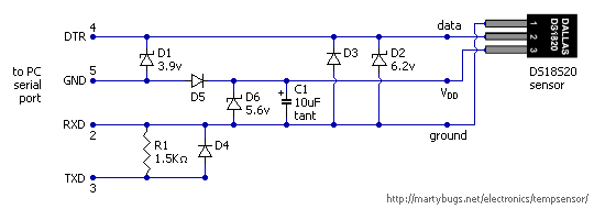
1-wire serial port interface circuit for non-parasitic mode operation
This version of the serial port interface circuit has three additional components - D5, D6 and C1, which are
used to provide power to the temperature sensor's VDD pin, rather than grounding
the VDD pin.
Component List - Non-Parasitic Mode Circuit
The following components are required for the non-parasitic serial port interface circuit:
- DS18S20 1-wire temperature sensor
- D1 3.9v zener diode (1N5228 / 1N4730)
- D2 6.2v zener diode (1N5234 / 1N4735)
- D3,D4 Schottky diode (1N5818 / 1N5819)
- D5 1N4148 signal diode
- D6 5.6v zener diode
- C1 10uF tantalum capacitor
- R1 1.5kohm resistor
- female DB9 serial cable
Construction Details
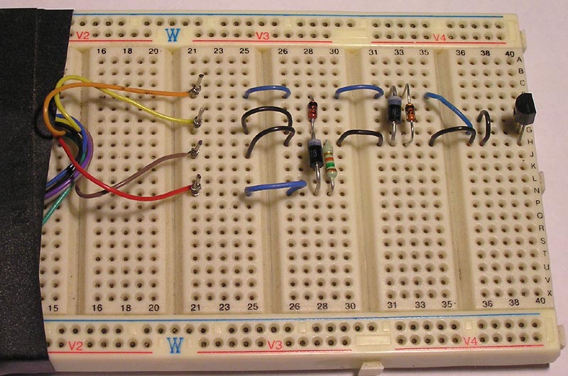
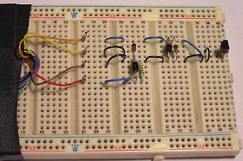
The serial port interface circuit can be prototyped on breadboard,
allowing you to confirm correct operation of the temperature sensor
and circuit before constructing a more permanent version.
| |
| |
parasitic mode interface circuit assembled on breadboard
|
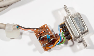
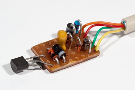
Once the operation of the circuit has been confirmed, it can be constructed on some
vero board, as shown in the photo below.
Vero board is ideal for this simple circuit, and allows for a relatively compact layout.
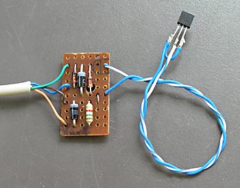
early prototype parasitic mode circuit on vero board
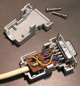
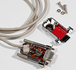
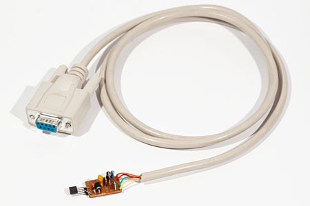
Circuit Inside A D9 Backshell
With some careful trimming of the vero board, it can be made small enough to fit
inside a D9 backshell, thus providing a very compact temperature sensor circuit.
A cable tie on the sensor wiring is used to provide strain relief, to prevent
the sensor wiring connections to the vero board being pulled off the board.
early prototype parasitic mode circuit, installed in a plastic D9 backshell
more compact parasitic mode circuit on vero board, fitted into a D9 backshell
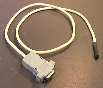
Installing the circuit inside a D9 backshell provides for a very compact
and robust serial port temperature sensor.
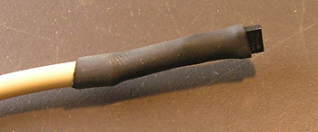
The sensor was soldered to the other end of the length of wire, with pins 1 and 3 of
the sensor being connected together. A short length of heatshrink is used to
insulate pin 2 from the other pins on the temperature sensor.
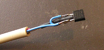
heatshrink over the sensor's centre lead
Another length of heatshrink is used to cover the wiring to the temperature sensor,
leaving the sensor protruding from the end of the heatshrink to ensure adequate
exposure to ambient air for temperature monitoring.
heatshrink over the sensor and wiring
Due to some additional components, the non-parastic mode circuit is slightly larger,
but can still be fitted onto a small piece of vero board.
non-parasitic mode serial port circuit on vero board,
with temperature sensor soldered directly to vero board
completed non-parasitic mode serial port sensor
If desired, additional temperature sensors
can be added in parallel, using longer lengths
of wire to attach them to the interface circuit.
This will allow multiple temperatures to be monitored at varying locations, with a single
serial port interface circuit.
last updated 24 Mar 2026
|