|
|
|
|
|
|
|
Conifer Antenna Testing
(first published May 2002)
This page details the testing method and results when comparing
a number of different Conifer dipole modifications.
Background
A number of different methods for modifying Conifer antennas for wireless
networking are documented on the 'net, and we came up with our own variation.
We decided to undertake some testing in a relatively controlled environment,
as this would allow us to compare the performance of the different modifications,
while trying to minimise the effect of any other variables on the results.
Test Equipment
We used two laptops, one at either end of our wireless link.
The specs for the laptop at the remote end:
The specs for the laptop at the antenna end:
- Pentium 150 with 64Mb RAM, 2.1Gb HDD
- Enterasys RoamAbout wireless card (with 6.04 firmware)
- Windows 95 OSR2
- Enterasys 7.44 drivers and client utility
- running on mains power (via an inverter in my car)
We had the following antenna hardware:
- 18dBi Conifer grid
- 24dBi Conifer grid
- 1.8m antenna mast
- 3 modified Conifer feedhorns
- 3 Conifer reflectors, each bent at a different angle
Each feedhorn had 2.5m of coax attached to it (measured from dipole to end),
terminated with a female N-connector.
Modified Feedhorns
We used three feedhorns in the testing, with each feedhorn being modified in a different way.
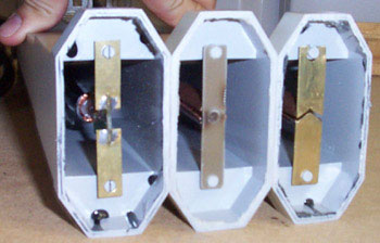
the three feedhorns (1 on left, 2 in centre, 3 on right)
Feedhorn #1 is the most commonly performed
modification,
utilising the original Conifer dipole, which has been cut off the down-convertor, with
the coax soldered to the PCB balun.
A 2.5m length of RG-213 coax has been used for this feedhorn.
Feedhorn #2 consists of a new balun constructed from copper pipe
and a galvanised nail, with the dipole constructed from a 61x12mm section of
PCB, with a 2.5m length of RG-213 coax.
Feedhorn #3 has a new dipole constructed from copper tube, brass tube
and brass plate, with the dipole length and balun length as close as possible
to 1/2 and 1/4 wave length respectively, and has a 2.5m length of CNT-400 coax.
Refer to my Conifer Antenna Modifications page for details
on constructing the dipole.
Antenna Reflectors
Three reflectors were used, to test how the reflector angle affects signal strength.
Reflector #2 was a "normal" reflector, ie, that's the reflector angle
as installed by Galaxy.
drawing showing the reflector angles used
As shown in the picture above, the angle of reflector #2 was such that
the edge of the reflector pointed towards the edge of the grid, while
reflectors #1 and #3 had sharper angles.
Reflector #2' is just #2 bent out slightly, as we decided to try this
configuration at the end of our testing.
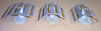
the three reflectors (2' on left, 1 in centre, 3 on right)
Test Setup
We placed the 486 laptop on the window sill on the 3rd floor of an office
building, with the wireless card configured for ad-hoc mode.
No external antenna was connected to this wireless card.
the test setup
We then set-up our test rig in a car park approx 300-400m away from the office
building, with clear line-of-sight to the laptop in the office, through a
gap in the trees.
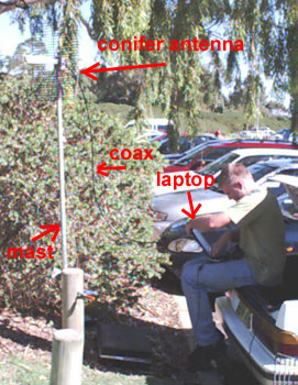
the test rig with 18dBi antenna on the mast
As we didn't want the mast to move during the testing, as this would introduce
additional variables and unknowns into the test results, we used an
F-clamp to clamp the mast to a convenient pole, and aimed the antenna at the office window.
For all tests, the antenna was mounted so it was horizontally polarised.
Note that the laptop in the office window did not have an external antenna connected,
so the polarisation of the antenna shouldn't matter.
Testing Methodology
A feedhorn was bolted to the grid, and a reflector attached to the end of the
feedhorn using some cable ties.
The antenna was connected to the wireless card in the laptop using an appropriate
pigtail, and the wireless card was configured to operate in ad-hoc mode, with
the same SSID as the other laptop.
All three reflectors were tested with each of the three feedhorns.
The "Link Test" mode in the Enterasys Client Utility was used to monitor the link strength,
with each test configuration being monitored for a couple of minutes.
the Enterasys Client Utility displaying link statistics
Once the reported link details had stabilised, the SNR, signal strength and noise
level were recorded for the P150 end of the link (ie, "This station" as displayed
above by the Client Utility).
Test Results
By holding the P150 laptop in the air, we managed to get a signal
using the only internal antenna in the wireless card.
|
SNR (dB)
|
2
| |
signal (dBm)
|
-92
| |
noise (dBm)
|
-95
|
Testing each of the reflectors with feedhorn #1 on a 24dBi Conifer grid:
|
reflector
|
1
|
2
|
3
|
none
| |
SNR (dB)
|
31
|
31
|
30
|
29
| |
signal (dBm)
|
-70
|
-69
|
-71
|
-73
| |
noise (dBm)
|
-101
|
-101
|
-100
|
-101
|
Testing each of the reflectors with feedhorn #2 on a 24dBi Conifer grid:
|
reflector
|
1
|
2
|
3
|
none
| |
SNR (dB)
|
31
|
32
|
32
|
29
| |
signal (dBm)
|
-70
|
-70
|
-69
|
-72
| |
noise (dBm)
|
-101
|
-101
|
-101
|
-101
|
Testing each of the reflectors with feedhorn #3 on a 24dBi Conifer grid:
|
reflector
|
1
|
2
|
3
|
2'
|
none
| |
SNR (dB)
|
35
|
35
|
33
|
33
|
31
| |
signal (dBm)
|
-66
|
-68
|
-66
|
-68
|
-71
| |
noise (dBm)
|
-101
|
-101
|
-100
|
-101
|
-101
|
Testing reflector #1 with feedhorn #3 on an 18dBi Conifer grid:
|
SNR (dB)
|
29
| |
signal (dBm)
|
-72
| |
noise (dBm)
|
-101
|
Conclusions
The test results clearly show that feedhorn #3 performs better
than the other two feedhorns.
However, it must be remembered that feedhorn #3 has a length
of CNT-400 coax, while the other two feedhorns are using RG-213 coax,
and the different loss characteristics of the the different types of
coaxes does affect the noise and signal levels.
According to this
antenna cable comparison chart,
CNT-400 has a loss of 22dB per 100m, while RG-213 has a loss of 49.9dB per 100m.
This means the 2.5m length of RG-213 has a loss of 1.25dB, while the 2.5m length of CNT-400 has
a loss of 0.55dB, ie, a difference of 0.7dB.
The test results indicate feedhorn #3 is achieving an additional 4 dBm in
signal strength, and about 4dB in SNR. Even taking into account the additional 0.7dB
gain due to lower loss coax, feedhorn #3 is achieving at least 3dBm better
signal strength than the other feedhorns, which is very encouraging, especially when
you consider that a 3dB gain is a doubling in signal strength.
The tests with the 18dBi Conifer show a signal stength which is 6dB less than
that achieved with the same reflector and feedhorn on a 24dBi Conifer, which
is the expected result.
Addendum: We've now performed some more antenna testing,
with a larger number of dipoles tested. See here for more details.
References
Modifying Conifer Antennas for Wireless Networking
Conifer Antenna Testing (part 2)
Credits
Photos by Marcus and
,
graphics by .
last updated 22 Oct 2013
|
|
|
|
|
|
|
|
|

