|
Anatomy of a 2.4GHz Rubber Ducky Antenna
(first published September 2005)
This page provides information on the rubber ducky antenna which is typically found
on most 2.4GHz 802.11 wireless network access points and routers.
As well as providing some historical information on the origins of the rubber ducky,
details are also provided of the anatomy of a sample antenna, based on photos taken
from a donor antenna which was disassembled.
The rubber ducky antenna is also commonly referred to as a rubber duck antenna, or
a rubber duckie antenna.
Overview
The rubber ducky antenna is a vertically polarised 360 degree omni-directional antenna.
They are compact, and due to the flexibility and rubber sheathing, are also very robust.
Due to its simplicity, the rubber ducky antenna is likely to be one of the cheapest and easiest
to mass-produce.
Early versions were sheathed in rubber, with more recent variations typically being
housed in a flexible plastic sheath.
While rubber ducky antennas can also be found on many portable RF appliances,
this page specifically relates to the rubber ducky antennas typically found
on 802.11 wireless network access points and routers.
I had a number of unused rubber ducky antennas, as all the APs
and routers that I've installed have
higher gain antennas
connected to them.
I decided to pull one apart, to see just what was inside.
Anatomy
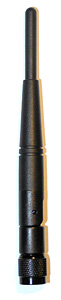
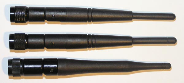
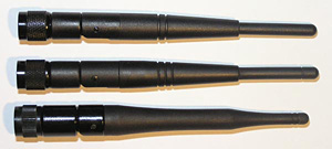
Some of the rubber ducky antennas I have collected:
| |
| |
|
various rubber ducky antennas
|
From top to bottom in the image above:
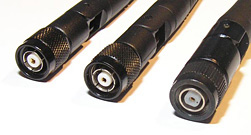
All three of these rubber duckies have an rpTNC (reverse polarity
TNC) connector.

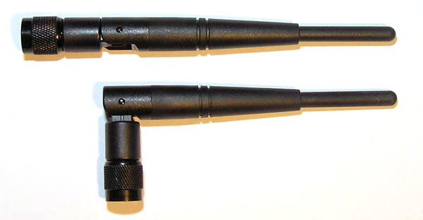
WRT54GS antenna detail
The antennas shown above are from a Linksys WRT54GS
wireless router, with an rpTNC connector,
and a flexible joint that allows it to be bent 90 degrees.
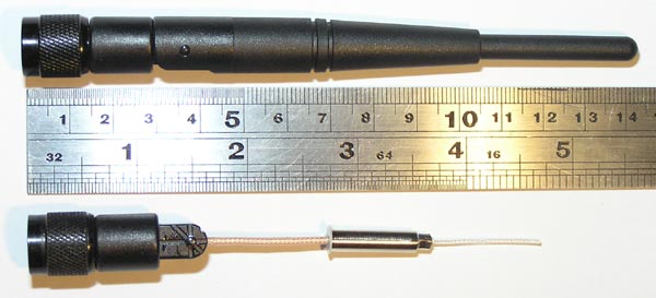
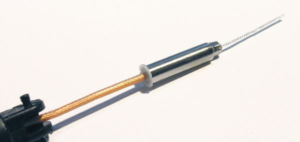
Stripping the plastic sheath off reveals the antenna hidden inside:

WRT54GS antenna detail
The length of thin wire whip protruding from the top of the metal casing
is approx 26mm, and the length of the metal casing is approx 24mm,
with a total length of 50mm.
An observant reader informs me that the metal casing is better known as the
"decoupler", and is typically used to tune the antenna,
by moving the decoupler up and down to vary the VSWR.

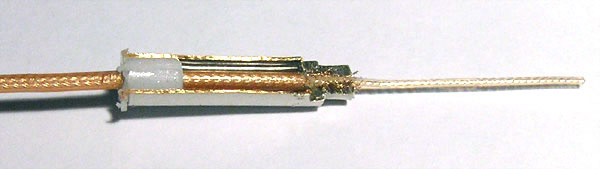
bare antenna element
A section of the metal casing was cut away, to reveal the coax inside it.
I was expecting a helical 1/4 wave antenna or similar to be hidden inside
the metal casing.
However, it's not as complex as that.
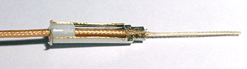
inside the antenna element
The cutaway view reveals that it is just a half-wave dipole antenna, with
one half of the dipole comprising of the metal casing, and the other
half comprising the whip extending from the top of the casing.
The bottom end (left end in the picture above) contains a plastic spacer,
and its sole purpose is probably to keep the coax centrally located inside the
metal casing.
The coax extends from the rpTNC connector at the base of the antenna, up through
the metal casing, and the top end of the casing has been crimped onto the
coax braid, to provide a solid electrical and mechanical join.
The centre core of the coax extends through this crimped join, and becomes the
whip at the top of the antenna.
Each half of the dipole is a 1/4 wavelength, with the length corrected based on
the velocity of the coax being used.
Assuming a centre frequency for 802.11b of 2.441GHz, a 1/4 wavelength in free space
is 30.7mm.
However, with this rubber ducky having a 1/4 dipole length of 26mm,
we can deduce that the velocity factor of the coax used is approximately 0.85
(ie, the same velocity factor as LMR400 coax, and also confirmed by other people's
test results).
When oriented vertically, the half-wave dipole has vertical polarisation,
with a radiation pattern resembling a donut shape, symmetrical 360 degrees in the horizontal plane,
and with a vertical beamwidth of approximately 75 degrees.
Note that rubber ducky antennas for lower frequencies (ie, CB, two-way radios, etc)
are typically not a half-wave dipole, as the lower frequencies mean a longer wavelength.
As a result, the physical size of a half-wave dipole for such frequencies would be
far too large to be convenient.
Rubber ducky antennas on such equipment are typically helical antennas, with a 1/4 wavelength
of wire wound around a coil.
The Name
There seem to be two conflicting ideas about the origin of the name "rubber ducky"
(or "rubber duck", "rubber duckie").
Because these antennas looked more like rubber than the usual stereotypical idea of an
antenna, the term "rubber ducky", popularised by the
Sesame Street
song sung by
Ernie,
was used to refer to these antennas:
Rubber Ducky, you're the one,
You make bath time lots of fun,
Rubber Ducky, I'm awfully fond of you;
...
The alternative
(and far less interesting, but probably more accurate) story is that
Caroline Kennedy coined the name when pointing to one on top
of a tranceiver being used by a secret service security guard.
Performance
Most rubber ducky antennas found on wireless APs and routers have a claimed
gain of about 2 - 2.2 dBi.
Test results and simulation results confirm that the gain of the half-wave dipole is
2.14dBi. That is, they have 2.14dB gain compared to a hypothetical isotropic antenna.
One easy way to improve the performance of these rubber ducky antennas
is to place a parabolic reflector behind the antenna, with the antenna
located at the focal point of the reflector.
This approach is detailed on the
Deep Dish Cylindrical Parabolic Template
website.
This will improve the gain of the antenna by focusing the transmitted signal,
thus increasing the directionality, decreasing noise, as well as enhancing privacy
by ensuring you're only sending the signal in the direction you want it to go.
However, a better way to improve the performance of an AP or router is to replace the
rubber ducky antenna with a higher-gain antenna, such as the
360 degree omni compact collinear,
the compact 11dBi biquad,
or a very directional dish.
Credits
All photos are copyright .
last updated 24 Mar 2026
|