|
Marcus' Mast & Antenna Installation
This page details the installation of a mast and antenna at Marcus' house,
providing him with a connection to the Hills Hub access point.
Parts Required
We used the following bits and pieces:
- 3m mast
- modified Conifer (ex Galaxy) 24dBi antenna
- ridge saddle to suit tile roof
- 3 guy wires
- 3 eye bolts
- coax
- silicone
We had previously obtained several 3m masts (including ridge saddle and guy wires)
when we were collecting Conifer antennas from people's roofs.
The eye bolts were purchased from a local hardware store, and we used about 10m
of RG-213 coax (this may yet be replaced with some CNT-400, to provide better
signal strength).
A PC with an Enterasys
RoamAbout wireless card, and an SVEC
WL-123 PCMCIA to PCI adapter,
running Red Hat 7.3, was targetted for use as a wireless router.
Testing
The Node Database
provides shows the location of access points, and also provides compass bearings,
distances, and elevation diagrams, and indicated that we should have line-of-sight
from Marcus' house to the Hills Hub access point.
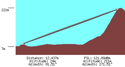
elevation diagram from the Node Database
Before installing the mast, needed to determine the best place to locate the mast on the roof.
Using a compass, we determined the direction of the access point
to which we wanted to connect .
With a laptop connected to the antenna, we climbed onto the roof, and pointed the
antenna in the general direction of the access point.
We used the RoamAbout Client Utility to monitor signal strength, and determined the
position on the roof which provided the strongest signal strength.
We found aiming the antenna was very important - a couple of degrees on either
side of the optimum direction, the signal would drop off significantly.
Installation
The saddle was placed on top of the ridge capping, and the mast temporarily located
on the saddle, and held upright.
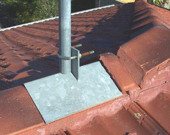
the saddle, positioned on top of the ridge
The three guy wires were straightened out, and appropriate locations on the roof for
the three eye bolts were determined.
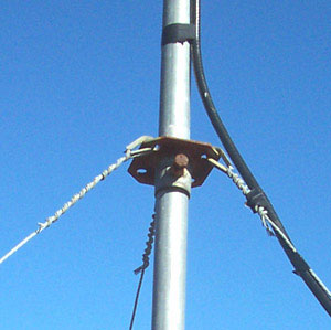
the guy wire attachment plate on the mast
A hole was drilled in the tiles for each eye bolt, ensuring each hole was directly
above a rafter.
After drilling pilot holes in the rafter, each eye bolt was screwed into place.
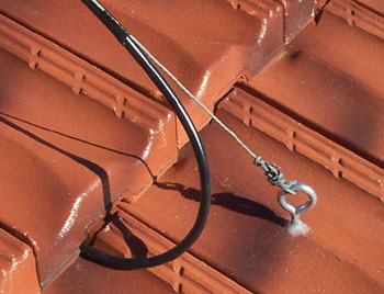
an eyebolt through the tile, and the coax disappearing into the roof
The mast was once again placed into position, and the guy wires were attached
to the eye bolts, holding the mast firmly in place.
The antenna was aimed towards the access point, and coax was run from the antenna,
down one guy wire, under a tile, into the roof space, and into the built-in robe
in Marcus' office (his server cupboard).
Electrical tape was used to attach the coax to the mast and to the guy wire,
and some silicone was used to seal the holes in the tiles for the eye bolts
against the elements.
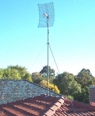
the mast and antenna, showing the three guy wires
After cutting the surplus coax, an n-connector was soldered and crimped onto the end
of the coax, and it was connected to a PC with a wireless card, via an appropriate pigtail.
While I monitored signal strength on a computer in the house, Marcus was on the roof,
adjusting the direction of the antenna. After a bit of trial and error, we
found the direction which provided the best signal strength, and the bolts
on the ridge saddle were tightened, to prevent any movement.
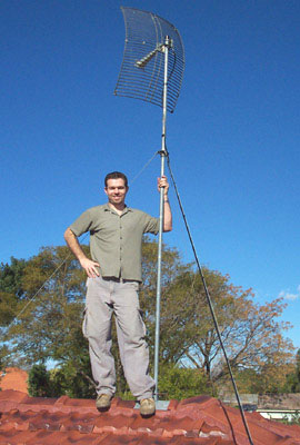
Marcus, standing on the roof next to his mast
The antenna has now been in place for several months, and has performed flawlessly.
The dipole modification we used (where we rebuild
the dipole from scratch using copper and brass) is definitely one reason
why we're getting good signal strength - careful testing
indicates it provides double the signal strength of the more common dipole
modification (where the PCB dipole is retained, and the coax soldered directly onto it).
References
Modifying Conifer Antennas for Wireless Networking
Conifer Antenna Testing
last updated 22 Oct 2013
|
|

